Details
Design Flow Solutions® offers complete
hydraulic analysis of complex piping systems including up to
9000 branches and 1000 tees. Network branches can consist of
any combination of pipe, fittings, and valves, with virtually
no limit on the number or type of components.
Both DF DesigNet® and DF Branch solve
networks using the Darcy-Weisbach formula together with Bernoulli's
theorem for liquids and the differential form of Bernoulli's
theorem together with numerical integration techniques for gases.
Both DF DesigNet® and DF Branch consider sonic flow and heat transfer limitations for gases. |
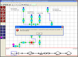
- Allows
rapid lineup changes (valves open and shut, pumps turned on
or off) and automatic recalculation of system values. Allows
analysis of normal and abnormal system lineups. Rapidly solves
"what if" problems.
- Allows
entry of absolute or relative elevations.
- Automatically
sizes pipe diameter to satisfy specific flow and pressure drop
criteria.
- Automatically
determines flow direction for each flow path in the network.
Adjusts flow resistance values to account for flow direction.
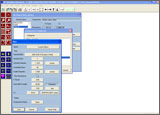
- Flow
rates can be specified using mass flow rate, volumetric flow
rate (actual or standard), or velocity, in any of the unit types
provided in the program or added by the user. The user can control
the display precision for each value.
- Supports
both imperial and metric units. Includes hundreds of unit types
(more can be added by the user), any of which can be used for
data entry and display.
|
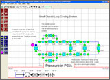
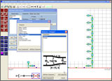
- Graphical
interface allows the user to build a complete network showing
all flow paths.
- Displays pressures, flow rates, fluid conditions,
and others at all points within the piping system. Symbolic
picture of branch hardware is displayed showing parameter values
throughout each branch.
|
- Titles,
labels, and user specified text can be displayed at any location
on the drawing. Multiple text sizes are permitted.
- Provides
a virtually unlimited drawing area. Complete user control over
drawing scale and text sizes. An optional grid assists in drawing
complex networks.
- Block
operations allow a portion of a drawing to be copied, moved,
or deleted in a single step.
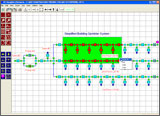
- Graphical
display is color coded to indicate whether data has been specified
by the user, determined by the program, or still unknown. Areas
limited by choke flow are also indicated.
|
- Includes
data on over 50 common liquids and gases. Properties, such as
density and viscosity, are provided for water, hydrocarbons,
freons, brines, alcohols, liquid chemicals, and gases and vapors.
Additional fluids can be specified during each use or added
to the database using the utilities. Fluid properties can be
specified using data points or equations. Real gas behavior
is modeled.
|
- Includes
piping dimensional specifications for standard carbon and stainless
steel piping. Data provided includes dimensions, surface roughness,
weight and volume per foot, and more. Pipes can be specified
using NPS or OD and schedule, or by specifying the internal
diameter. Program calculates Reynolds number and friction factor
as needed for problem solution. Additional specifications can
be created and used.
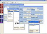
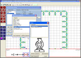
- Standard
hardware includes numerous types and geometries of common valves
(globe, ball gate, butterfly, plug, check), common fittings
(elbows, bends, others), several types of orifices and nozzles,
and more. Pictures of standard hardware are provided which illustrate
important dimensions. Flexible entry of required parameters
(for example, orifice throat diameter can be specified as actual
size, flow area, or ratio of throat size to inlet size). Similar
entry is permitted for other values.
- Determines
pipe service pressure rating for a specified pipe material,
design temperature, pipe wall allowance, and manufacturing tolerance
in accordance with ANSI B31.1 and B31.3 and plastic pipe design
criteria. Program contains material data for common carbon and
stainless steels. Additional material data is available or can
be added using the utility package.
- Allows
entry of user-specified components. Components can be specified
using fixed resistances (Cv, L/D, or K factor), or resistances
that are a function of flow rate, size, or any arbitrary parameter
specified by the user. Graphical display of size, flow, and
parameter dependent data are provided.
- Allows
use of positive displacement or centrifugal pumps. Utilities
create pump data files using head versus flow data specified
by the user. Graphical display of the calculated head/flow curve
and input data is provided.
- Supports
sharp-edge, thick, rounded-edge, and beveled orifices with the
same or different inlet and outlet pipe sizes. Automatic sizing
of orifice throat diameters to produce desired flow/pressure
drop characteristics.
 |  |
 | |
|
- Provides
detailed warnings to ensure accurate system modeling. Monitors
for items including cavitation (water systems), disc lift in
check valves, sonic flow, and others.
- Includes
a variety of printed reports ranging from summary to detailed.
Detailed reports contain all calculated values and equations
used in the solution. Report choices include graphical display
of problem and branch hardware. Reports allow rapid verification
of calculated results. Text results can be output to printer
or to file.
- Stores
descriptive information for branches and networks. Reports can
include a cover page with descriptive information.
|
|
|
|
Home |
Login
|
|
© 2010 - ABZ, Incorporated | 4451 Brookfield Corporate Drive Suite 107 Chantilly VA | 800-747-7401
|
|